

2026-03-16

A Guide to Common Fault Diagnosis and Systematic Handling of Embroidery Machines


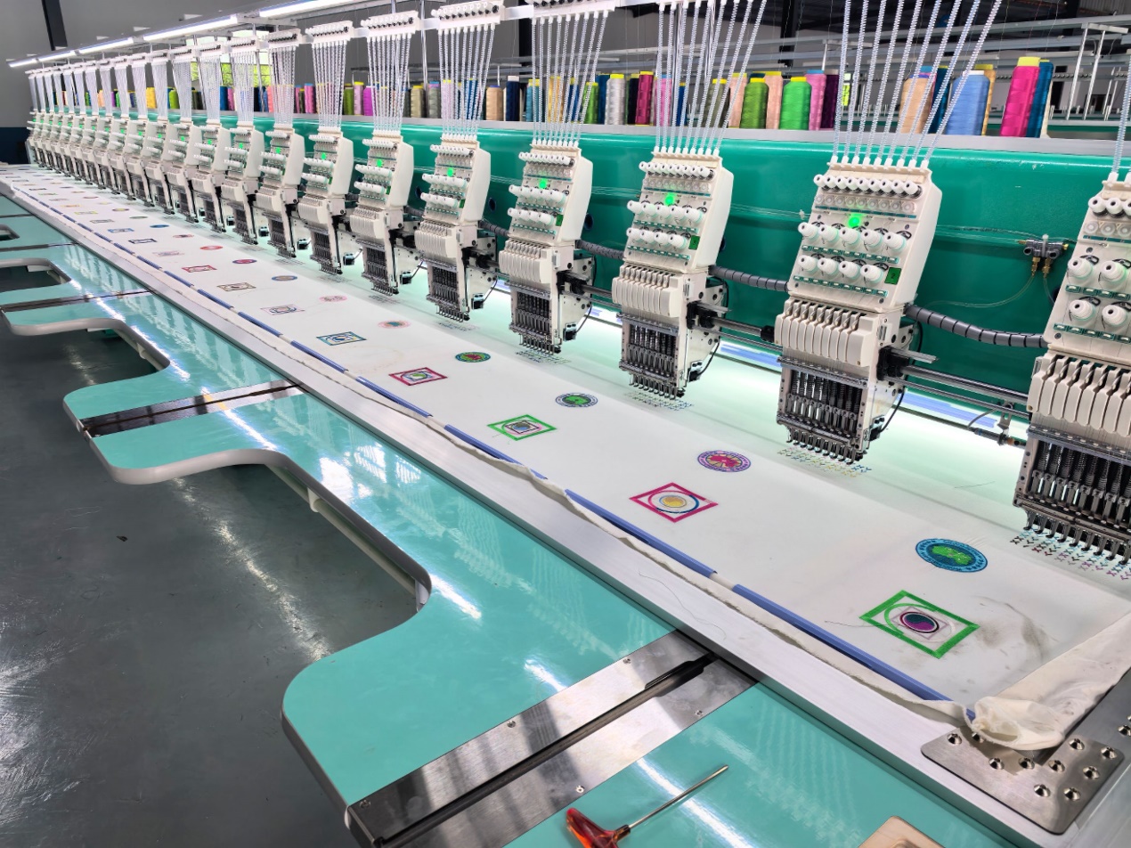
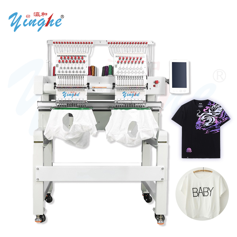
During the long-term operation of embroidery machines, typical faults such as thread breakage, thread jamming, needle breakage, needle skipping, loose thread, and pattern displacement may occur due to mechanical wear, parameter deviation, insufficient compatibility of consumables, or environmental factors. Although these problems share commonalities, their causes vary. Therefore, it is necessary to classify and accurately intervene based on the characteristics of the phenomena. This guide, based on practical experience on the front line and the principles of the equipment, systematically sorts out the diagnostic logic and standardized handling procedures for six major types of frequent faults, aiming to help operators enhance their independent troubleshooting capabilities, reduce unplanned downtime, and ensure the stability of production and the consistency of embroidery quality.
I. Thread Breakage Faults: Distinguishing Regular and Irregular Causes
Thread breakage is the most common fault in embroidery machines. It is necessary to first classify it into regular and irregular thread breakage based on the location, frequency, and reproducibility of the breakage to clarify the troubleshooting path.

Regular disconnections (with highly consistent disconnection points and timing) are often caused by a decline in mechanical fit accuracy or component damage. It is recommended to check the following items in sequence:

- Abnormal fit clearance between the needle and the shuttle (such as the needle position being too high or too low), requiring re-calibration of the needle bar height and shuttle phase;
- Burrs or scratches on the needle hole, needle plate hole, shuttle surface or positioning hook, causing damage to the embroidery thread due to scraping, which should be smoothed with fine sandpaper or a dedicated polishing tool;
- Burrs, dirt accumulation or deformation on parts such as the thread guide plate, thread take-up lever guide hole, and upper and lower thread guides in the thread path, affecting the smoothness of the stitch, and it is advisable to clean, grind or replace the corresponding parts;
- Incorrect installation direction of the needle, bent needle tip or surface with glue stains/oil stains, requiring replacement with a new qualified needle and strict installation according to the specifications;
- Wear of the thread take-up cam, axial movement of the shuttle shaft or damage to the shuttle thread passage surface, requiring replacement of the worn parts and re-calibration of the transmission synchronization.

2. Irregular disconnections (random breakpoints, no obvious periodicity)
This is often related to external conditions and process parameters. Prioritize checking the following aspects:
- Excessive environmental humidity causing the embroidery thread to absorb moisture and expand. It is recommended to activate dehumidification equipment and replace it with new, dry, and tension-stable threads of the same specification.
- Unreasonable needle path design in the pattern file (such as too many sharp turns or overly dense stitch spacing). Work with the pattern-making engineer to optimize the stitch logic.
- Mismatch between the embroidery thread's diameter, twist, or strength and the needle model. Select high-quality embroidery threads that are compatible with the equipment manual and standardize the threading process.
- Improper setting of the dynamic frame acceleration curve or frame movement angle parameters. Use the standard parameter template in the control system and fine-tune for verification.
- Asynchrony between the machine head and the shuttle, commonly caused by increased gear clearance in the upper and lower shafts, loose or broken timing belts, or unbalanced chain tension. Check the gear box status and calibrate the transmission timing.
- Excessively high surface friction coefficient of the embroidery thread. Apply a thin layer of food-grade silicone oil evenly before winding (avoid over-application) to improve the thread's lubricity.


II. Thread Jamming Fault: Essentially, it is the entanglement of the bottom thread, which is an early warning signal.
Thread jamming is characterized by the bottom thread abnormally entangling into a ball under the needle plate, blocking the needle hole and eventually causing thread breakage. This phenomenon is an early indication of an imbalance in the tension system or abnormal mechanical coordination of the equipment. It requires prompt response and should not be dealt with only after the thread breaks.

1. The gap between the positioning hook and the shuttle frame notch exceeds the tolerance range (the standard value is usually 0.05–0.1 mm). A gauge should be used for detection and fine adjustment.
2. The fabric weight is too light, the tension of the frame is insufficient, or the needle plate hole diameter is too large, resulting in the bottom thread not being effectively tightened. It is recommended to add 1–3 layers of non-woven fabric on the back of the fabric to enhance the support rigidity.
3. The action of the thread locking mechanism fails (such as the solenoid valve response is sluggish or the thread locking rod is stuck). The airway/electrical interface should be cleaned and the movement stroke of the actuator should be checked.
4. The bottom thread tension is too loose and the thread exit angle deviates from the design benchmark (the ideal exit angle is 90°±5°). The bottom thread tension value should be reset and the shuttle case installation position should be corrected.
5. Fiber debris, oil sludge, or slight deformation is embedded in the shuttle case, causing increased resistance to the rotation of the shuttle core. Dust and dirt should be cleaned in time. If the deformation is irreversible, the original factory-certified shuttle case must be replaced.


III. Broken Needle Fault: The main cause lies in inaccurate dynamic fit, not merely a problem with consumables.
Most broken needles are caused by abnormal lateral stress on the machine needle during high-speed reciprocating motion, and rarely by material defects of the needle body. A systematic investigation should be conducted from three aspects: installation, fit, and tension.

1. If the needle body has an imperceptible micro-bend to the naked eye or the tight needle screw has not reached the rated torque (recommended torque value: 0.8–1.2 N·m), a new needle should be replaced and tightened with a torque wrench as per the specification.
2. If the gap between the needle and the shuttle is less than the safety threshold (usually < 0.03 mm), causing periodic collisions, a special gap gauge should be used to reset it.
3. If the top thread tension is too high, causing the needle bar to be obstructed during its downward movement and resulting in an excessive instantaneous bending moment, the pressure of the thread clamp plate should be gradually reduced and tested by sewing.
4. If the presser foot hole, needle plate hole and the center axis of the needle are not three-point concentric, with a deviation > 0.1 mm, it is prone to cause eccentric loading and breakage. A concentricity calibrator should be used for adjustment.
5. In rare cases, if the X/Y-axis acceleration or positioning accuracy in the frame movement parameters is set beyond the limit, causing the frame's inertial impact to be transmitted to the needle bar, a stable motion curve should be called in the control system.
6. In very rare cases, it may be due to poor heat treatment of the needle. It is recommended to uniformly use industrial-grade needles provided by ISO 9001 certified suppliers.
7. If the radial or axial positioning of the shuttle is offset, causing the needle tip to fail to accurately enter the shuttle's thread-catching area, the shuttle assembly should be disassembled and the reference reset according to the maintenance manual.


IV. Thread Jumping Fault: The Core Issue Lies in the Failure of Needle and Thread Coordination and Fabric Constraint
Thread jumping is characterized by the top thread not being effectively secured by the bottom thread, resulting in a single thread floating on the fabric surface, which directly affects the integrity of the pattern. The fundamental causes are mainly attributed to the disruption of the synchronization between the needle and thread movement and the insufficient dynamic constraint of the fabric.

1. If the phase of the needle and the rotary hook is out of alignment (the needle tip does not enter the hook mouth synchronously when it reaches the lowest point), focus on calibrating the verticality of the needle bar and the zero position of the rotary hook.
2. If the rotary hook body has cracks, tooth wear or dynamic balance failure, a new rotary hook that has passed the dynamic balance test must be replaced.
3. If the needle bar return spring is fatigued and broken or its elasticity is reduced, causing the needle bar to rebound slowly, a custom spring that meets the original factory specifications should be replaced.
4. If the tension of the frame is lower than the process lower limit (it is recommended to be ≥ 30 N/cm²), causing the fabric to shift with the movement of the needle bar, a digital tension meter should be used to monitor and tighten it in real time to meet the standard.
5. If the presser foot height exceeds the standard (the standard gap: when the needle is at the lowest position, the distance between the bottom of the presser foot and the needle plate is 0.5–1.5 mm, set according to the thickness gradient of the fabric), or the bottom of the presser foot is deformed, causing local suspension, the height should be calibrated or the presser foot assembly should be replaced.


V. Floating Thread/Loose Thread Fault: A Combined Manifestation of Tension Imbalance and Insufficient Lubrication
Floating thread refers to the situation where the top thread or bottom thread does not fully embed into the fabric fiber layer and instead arches on the fabric surface. It is a typical tension control fault and can usually be quickly restored through minor parameter adjustments and basic maintenance.

1. The tension of the top thread and the bottom thread has not formed a reasonable matching relationship (the conventional ratio is 1:1.2–1:1..5). The tension screws of the thread clamps and the shuttle case need to be adjusted respectively, and the smoothness of the stitch should be verified by continuous embroidery on a standard test fabric for 3 minutes.
2. If the embroidery thread structure is loose, the tensile modulus is low or the oil content is abnormal, it is recommended to replace the high-twist polyester embroidery thread that meets the GB/T 2912.1–2019 standard.
3. If the lubricating grease inside the rotary shuttle dries up or gets contaminated, causing an increase in rotational resistance, it is suggested to use special white oil (ISO VG10) to lubricate the bearings and the thread passage surface of the rotary shuttle at fixed points every shift, with a single application amount of no more than 0.05 mL.


VI. Pattern Shift and Deformation: Indicating Deterioration of Mechanical Transmission System Rigidity
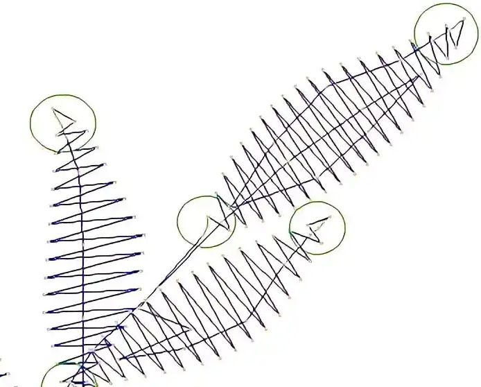
Overall pattern offset, stretching deformation or local misalignment essentially reflect the decline in positioning accuracy of the X/Y-axis servo system. The corresponding transmission chain should be locked down for root cause analysis based on the direction of displacement.

1. Systematic offset in the X direction: Focus on checking issues such as loose couplings of the X-axis stepper motor, abnormal tension of the timing belt (deflection > 2 mm), excessive play in the timing wheel bearings (> 0.02 mm), wear of the rhombic bearings, and excessive clearance in the guide rails of the tensioning frame blocks (> 0.03 mm). Tighten, tension, replace or adjust them in sequence.
2. Systematic offset in the Y direction: The failure mechanism is exactly the same as that in the X direction. Only the inspection items need to be transferred to the corresponding components of the Y-axis.
3. Global displacement or distortion: This indicates a compound failure in the main drive system (such as gearboxes, synchronous pulley sets, linear guide pairs). A full system accuracy test (it is recommended to use a laser interferometer) must be carried out, and a graded repair plan should be formulated based on the test report.


Conclusion: Prevention is better than correction
Among the aforementioned faults, approximately 85% are attributed to the negligence in daily maintenance, including the lack of lubrication for the shuttle, the overuse of the needle beyond its service life, the accumulation of foreign objects in the shuttle case, and the failure to regularly tighten the transmission components. It is recommended to establish a standardized inspection checklist (including daily cleaning items, weekly lubrication items, and monthly precision calibration items), and incorporate key parameters (such as tension values, frame tension, and frame movement acceleration) into the equipment operation log for trend management. Through a proactive, data-driven, and standardized operation and maintenance strategy, the overall equipment efficiency (OEE) can be significantly enhanced, the service life of core components can be prolonged, and the long-term stability of embroidery quality can be guaranteed.