
2026-07-17

Professional Installation & Commissioning Practical Guide for Commercial Embroidery Machines

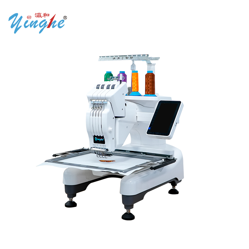
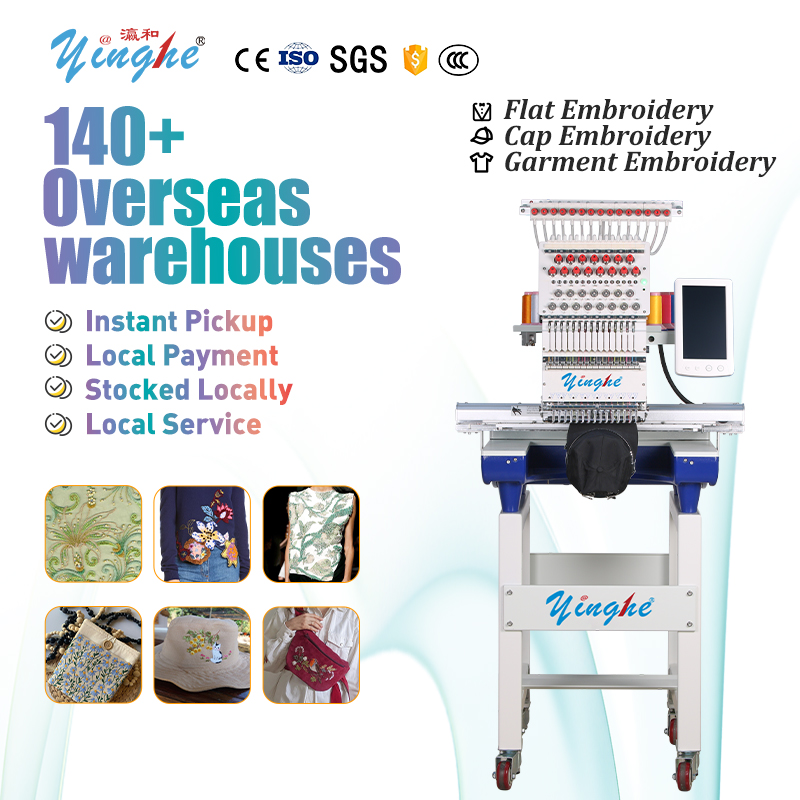
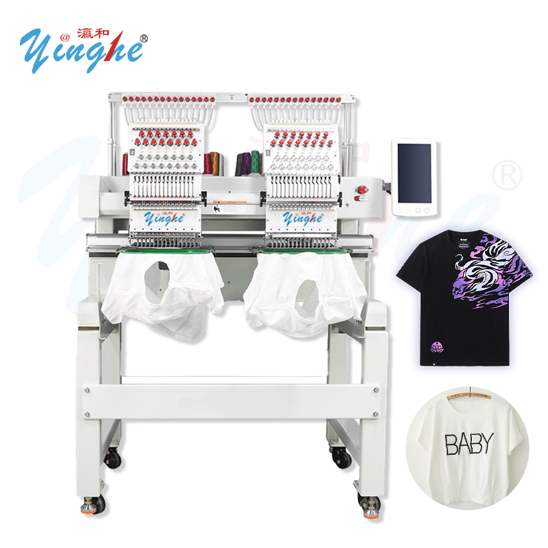
Applicable Models: Single-head and two-head home/small commercial computerized embroidery machines (non-pneumatic).
Objective: To provide field technicians with a standardized, data-driven, and fault-diagnosable installation and commissioning process, ensuring first-pass acceptance and preventing common issues such as skipped stitches, thread breaks, pattern misalignment, and abnormal noises.
1. Pre-Installation Conditions: Site & Environment Verification

1.1 Floor and Space Requirements

Floor Type: Prefer indoor, flat, rigid surfaces (cement, solid wood flooring, or smooth tiles). Prohibited: Soft carpets or uneven ground.
Clearance Space:
  • Front: ≥ 1.2 m, for hoop entry/exit and fabric handling.
  • Rear: ≥ 0.8 m, for cable routing and control box ventilation/access.
  • Left & Right: ≥ 0.5 m each, to ensure the head beam and XY frame have full, unobstructed travel.

1.2 Environmental Specifications

Temperature & Humidity: Operating temperature strictly between 18°C – 30°C; relative humidity ≤ 80%.
Cleanliness: Avoid direct sunlight, water accumulation, oil/grease, and areas with heavy lint/dust. Thoroughly clean the installation area beforehand to prevent debris from clogging guide rails and sensors.

2. Power Supply Installation (Critical)

Small machines are highly sensitive to voltage fluctuations. Incorrect wiring is the primary cause of board burnout and step loss. Strictly follow these standards.

2.1 Electrical Parameter Standards

Rated Voltage: Single-phase 220V AC ± 10% (permissible range: 198V – 242V).
Dedicated Circuit: Must use a dedicated 3-pin socket and an independent 16A/2P residual-current circuit breaker (RCCB). Prohibited: Sharing the circuit with high-power devices such as sewing machines, irons, or fans.
Cable Gauge: For equipment power ≤ 1.5 kW, copper conductor cross-section ≥ 1.5 mm².

2.2 Mandatory Grounding (Important)

Grounding Resistance: Must be reliably connected to earth, with resistance ≤ 4Ω. (If measurement is unavailable, ensure connection to the building's dedicated grounding terminal bar.)
Prohibited Actions: Never connect the ground wire to the neutral wire or water pipes. Omitting the ground lead is the most common hidden cause of main board failure due to static discharge.

2.3 Voltage Stabilization

If site voltage fluctuates frequently, a voltage stabilizer must be installed to protect the control system and servo motors. Failure to do so will void warranty coverage for pattern drift issues.

3. Tools & Pre-Installation Machine Inspection

3.1 Tool Checklist

Spirit level, full set of hex wrenches, Phillips/flathead screwdrivers, needle-nose pliers, tape measure, cleaning brush, lint-free cloth.

3.2 Consumables for Test Sewing (Standby)

Compatible needles (recommended #75/80), top thread, bobbin thread, embroidery backing paper, plain cotton fabric.

3.3 Removal of Shipping Restraints (Mandatory)

Remove all shipping brackets, cable ties, limit blocks, and head packing foam. Confirm all moving parts are unlocked and free.

3.4 Visual & Mechanical Inspection

Mechanical Parts: Needle bar, rotary hook, oscillating levers, XY guide rails, and timing belts must be free of dents, deformation, or looseness.
Electrical Parts: Control box connectors, data cables, and motor terminal plugs must be secure and undamaged.
Manual Feel Check: Gently push the hoop frame along both X and Y axes through its full travel. Motion should be smooth, with no sticking or abnormal resistance.
4. Machine Frame Leveling & Fixing

Frame leveling is the physical foundation for accurate pattern registration. A tilt of just 0.5° can cause noticeable misalignment.

4.1 Leveling Procedure

1. Position the machine and loosen the locking nuts on the adjustable feet.
2. Place the spirit level on the head mounting surface (horizontal) and the guide rail beam (longitudinal).
3. Adjust the feet until both the horizontal and vertical bubbles are centered (visual error ≤ half a division).
4. Confirm all four feet are firmly on the ground with no rocking, then tighten the foot locking nuts.

4.2 Travel Re-Check

After leveling, manually move the XY hoop through its full range again to ensure no new friction or interference has been introduced.

5. Lubrication & Mechanical Initial Setup

Factory-preservative oils are not working lubricants. They must be cleaned off and replaced with proper operational oils.

5.1 Lubrication Points & Oil Specifications

Lubrication Point Oil Type Application Standard
Needle bar, pivot pins, rotary hook raceway Sewing machine oil (light/white oil) Apply 2–3 drops to form a film; hook wick must be saturated but not dripping
XY rails, sliders, gears, bearings Lithium-based grease Apply a thin, even coating; inject 1–2 strokes into grease nipples
Strictly Prohibited Mixing oil types or using inferior oil Causes clogged oil paths or thermal breakdown

5.2 Post-Lubrication Cleanup

After lubrication, manually turn the main shaft 2–3 revolutions. Wipe off excess oil from rail surfaces and the needle bar using a lint-free cloth to prevent oil spray during high-speed operation.

5.3 Manual Hand-Wheel Pre-Check

Slowly and steadily rotate the main hand-wheel through a full cycle while checking:
  • Synchronized, interference-free motion of the needle bar, rotary hook, and take-up lever.
  • Absence of metallic knocking or intermittent sticking sounds from the head.
If any abnormality is found, stop and clear the mechanical interference immediately. DO NOT power on, as this may burn out the motor.

6. Electrical Connection & Power-On Pre-Check

Follow the principle: Connect first, then power on; test no-load first, then loaded.

6.1 Cable Connection

Plug in all connectors (control box, head motor, XY drive motors, sensor cables) firmly until the locking clips engage securely—no loose or partial connections.
Route and tie cables neatly, keeping them away from timing belts and moving guide rails to prevent chafing.

6.2 First Power-On Procedure

1. Emergency Stop Check: Confirm the E-stop button has been twisted clockwise to the released (popped-up) position.
2. Switch On: Observe the control panel lights up, system self-check passes with no error codes, and motors idle without abnormal high-frequency hum.
3. Home/Limit Test: Execute a mechanical home return and verify accuracy. Manually trigger each limit sensor and confirm the screen displays the corresponding signal. Faulty limit sensors will cause frame crashes—this must be resolved before proceeding.

7. Core Timing & Process Parameter Tuning

This is the heart of machine accuracy. All adjustments must be done manually via hand-wheel rotation; never adjust the rotary hook while the machine is powered.

7.1 Needle Position & Rotary Hook Timing Calibration (Critical Data)

Calibration Item Standard Value / Procedure Consequence if Incorrect
Needle Bar Bottom Dead Center (BDC) Turn hand-wheel to lowest point. Gap between needle eye top edge and inner hook raceway: 0.5–1.0 mm (approx. thickness of heavy paper) Too large → skipped stitches; too small → needle/hook collision
Rotary Hook Take-Up Timing When needle rises 2.2–2.5 mm from BDC, the hook tip must precisely catch the loop bulge Too early → thread breaks; too late → skipped stitches
Presser Foot Height Regular fabric: 6–8 mm from needle plate; increase for thick material, decrease for thin Too high → fabric floats; too low → fabric drags

7.2 Thread Tension Calibration

Bobbin Tension: Hold the bobbin thread end and lift gently. The bobbin case should descend slowly and smoothly, not free-fall (approx. 15–20g pull force).
Top Thread Tension: Adjust the tension nut. The optimal setting shows the bobbin thread just barely visible from the underside, without the top thread exposing white.
Rule of Thumb: Too tight → frequent breaks; too loose → loose loops and uneven stitches. A balanced, flat stitch line is the target.

7.3 Control Parameter Settings (Break-in Period)

Parameter Recommended Value (First 300 hours) Note
Max Embroidery Speed ≤ 650 SPM (70% of rated max) Medium-low speed break-in extends lead screw/rail life
Start/Stop Compensation Enabled, use factory default values Eliminates start/stop density variations
Thread Break Detection Sensitivity Set to Mid-level Too sensitive → false stops; too insensitive → missed breaks
Auxiliary Functions Disable all pneumatic/large-machine options Prevents redundant software errors

8. Test Run & Acceptance Procedures

Complete acceptance in two stages before delivery.

8.1 No-Load Test Run

No fabric, no threading. Run a standard test pattern cycle for 20 minutes.
Pass Criteria: Head and frame run smoothly—no abnormal vibration, no gear noise. Home position repeatability error ≤ 0.1 mm.

8.2 Actual Sewing Test & Acceptance

Mount fabric and backing, thread the machine. Select a test pattern combining squares, circles, and standard serif text.
Pass Criteria: Continuous sewing for 20 minutes with zero thread breaks. Stitches are uniform; square corners are perpendicular; circles are perfectly round; text strokes do not overlap.
Post-Test Cleaning: Use a brush to remove lint from the table and rails. Wipe off oil residue from the machine body with a cloth. Neatly dress external cables.

8.3 Quick Troubleshooting Reference Table for New Machine Test Sewing

Symptom Primary Check (in order) Secondary Check
Skipped stitches at start / thread pull-out ① Hook timing (2.2mm rise) ② Top tension too loose ③ Bent or reverse-mounted needle
Frequent thread breaks (within 10 stitches) ① Burr on needle plate or hook raceway ② Top tension too tight ③ Needle size too small
Pattern shifts horizontally / overlaps ① XY belt tension ② Loose home sensor ③ Unstable motor drive current
Unusual noise during frame movement ① Dry rails or foreign debris ② Worn timing belt inner surface ③ Loose motor mounting screws

9. Safety Prohibitions & Delivery Handover Notes

1. Absolute Prohibitions:
  • Never power on without a ground wire.
  • Never run the machine on an unlevel surface.
  • Never skip the manual hand-wheel pre-check and jump directly to high-speed operation.
2. Break-in Prohibition: During the first 300 operating hours, never run continuously at full high speed (≥ 800 SPM). Damage caused to guide rails and drive components under this condition is not covered under warranty.
3. Structural Prohibition: This machine has no pneumatic design. Never install aftermarket air lines or modify the frame structure, as this will compromise stability and void the warranty.
4. User Handover Instructions: Verbally instruct the end-user on daily maintenance—remove lint from the hook area after each shift, apply light oil to guide rails weekly, and cover the machine with a dust cover during extended idle periods.
Closing Note (Optimized Version) : This guide eliminates redundant explanations and provides actionable data plus a logical troubleshooting framework. By following the sequence and consulting the troubleshooting table when issues arise, field technicians can ensure a first-pass qualified installation and stable, reliable machine handover.